Linking Definitional Models (SysML) to Executable Architectures
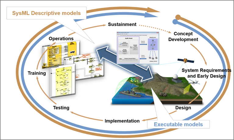
Through this example we intend to demonstrate the current capability of linking formal, definitional models (SysML) to executable architectures, providing bidirectional traceability from specifications and requirements to system performance and deployed systems. This framework provides the architecture to integrate software development into the modeling environment, allowing the SysML to orchestrate the model and software generation activities (whether machine or human created). The end result is a more robust product, truly reflecting the design intent, that has been rigorously validated in mission simulations continuously throughout the development lifecycle (Figure 5.1).
The integration and extension of Commercial of the Shelf (COTS) tools allows us to construct the framework described previously. The act of integrating executable models directly into the formal descriptive models gives users the ability to track performance impacts of system design modifications as they occur and more tightly couples the Systems Engineering and Software Development phases.
Our vision is to enable a fully connected Digital Thread with a consistent physics-based mission environment at the core. By executing formal model-based System-of-Systems interactions in this mission environment, the true Mission Digital Twin is created. As system models evolve throughout the product lifecycle, they can be re-exercised and reevaluated within the common mission environment alongside other systems. This enables continuous (and automated) assessment of the impact each change has on the overall mission objectives. Integrating the mission environment and operational objectives into the Digital Thread early and throughout the entire product lifecycle provides an opportunity to discover and resolve critical issues in a timelier fashion.
To illustrate the workflow, consider the example of a CubeSat space weather experiment and how it
progresses through the engineering lifecycle. This paper will demonstrate the value of bidirectional
traceability by connecting the requirements to the analytical models through the descriptive model. The
ecosystem for this demonstration will contain a SysML modeling environment (NoMagic Cameo), a tool
orchestration layer (Phoenix Integrations ModelCenter and AGI UFOS) and a mission simulation
environment (AGI STK).
Every new program is initiated by a need for a new mission capability. Our example CubeSat mission is
motivated by improving awareness of the atmospheric conditions and their relation to climate change.
That need shapes our initial concept, dictating a variety of requirements (in our case: orbit geometry,
payloads, etc.). We capture that through the MBSE process. SysML has the responsibility for being the
authoritative system model, providing the traceability from requirements, through architecture, to
behaviors and performance. A rigorous MBSE process requires that the model is truth, such that the
model can be relied on for all questions about the construction or performance of the system.
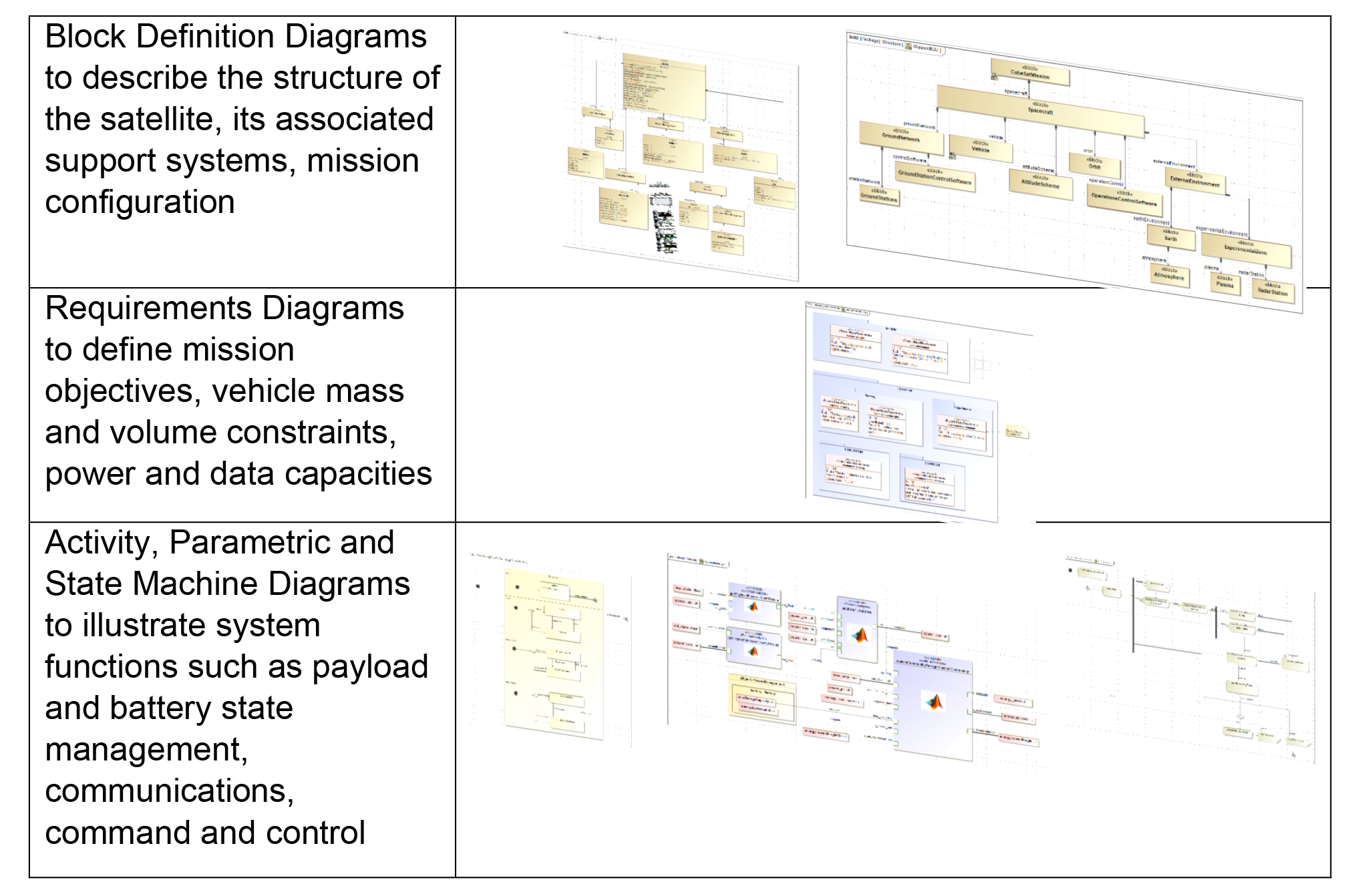
The CubeSat project begins with a formal model description in SysML (Figure 5.2):
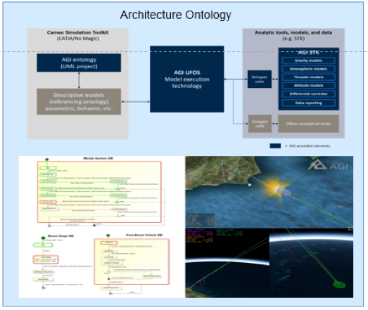
There is also an underlying Architecture Ontology employed (Figure 5.3), a formal representation of the knowledge of concepts within and across the architecture’s domains, in addition to the relationships between those concepts. This includes Types, Associations, Events, Behaviors, and Instances. The ontology serves as a foundation for a number of key elements in this framework. First, it will formalize the nomenclature in the Architecture so that it is consistent. Second, the ontology’s formalisms enable its execution. Last, it enables the utilization of any appropriate tools to be integrated into this framework. Currently, AGI’s COTS ontology has evolved to provide formal models for Space and Core domains. Its standards-based approach enables Customers to modify or write their own models.
To ensure future DevSecOps software strictly adheres to the model, a link is established from the SysML to the executable environment through an “orchestration layer”. This link extends traceability to the system’s performance and back to requirements, completing the feedback loop.
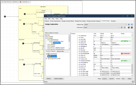
ModelCenter is the orchestration layer integrated into the SysML environment (Cameo). It provides a common interface for wrapping tools and algorithms (commercial and custom/proprietary) and then orchestrates custom workflows by linking those tools and passing information. These workflows are the executable models that are linked into the SysML model through ModelCenter’s MBSE extension. From within Cameo, the interface of each diagram is matched with the corresponding interface in the ModelCenter workflow. The SysML diagrams already describe any relationships that exist between components, values and requirements. This allows the ModelCenter interface to discover relationships between evaluation parameters in an executable diagram back to any requirements they satisfy (Figure 5.4). These requirements can now be evaluated through executing the workflow and computing the system performance – the interface compares the result to the requirement and displays the pass/fail criteria as well as the margin.
The architecture described here requires an underlying physics-based environment for modeling the interactions between the assets as dictated by the formal models. Typically, a systems engineer must not only create the functional model for the component he or she is designing, but also for the environment to stimulate that component model. This necessitates constant updates to the environment model to align with the current fidelity of the component model or as components are integrated together into a larger system. Each update has the potential to add uncertainty to the results, obfuscate insight into the process, and increase timelines of the development lifecycle.
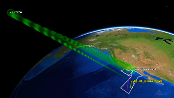
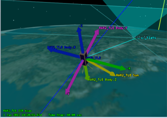
STK provides a flexible, high fidelity, physics-based modeling environment where formal system models can be exercised with other system models regardless of their current fidelity requirements (Figure 5.5). Much like Test Driven Development, where the test cases are constructed up front and the code is developed to pass the test, STK provides Mission Driven Engineering where mission requirements can be captured through very specific “scenarios” and systems or components can be engineered until requirements are satisfied. The environment supports models as they grow in complexity from low fidelity “stand-ins” for components lacking complete definition (in our CubeSat example geometric field of view, great arc vehicle routes, etc.) to full fidelity hardware-b
ased simulators and/or actual DevSecOps code. The utilization of a consistent modeling and simulation environment throughout the lifecycle ensures that changes in system performance metrics are due to modifications in the system design, not inconsistencies in the underlying modeling environment.
At the completion of the concept development stage, there is already an integrated mission simulation environment with executable system/component models embedded into the SysML model. This full loop connectivity provides the architecture for the remainder of the engineering lifecycle activities.
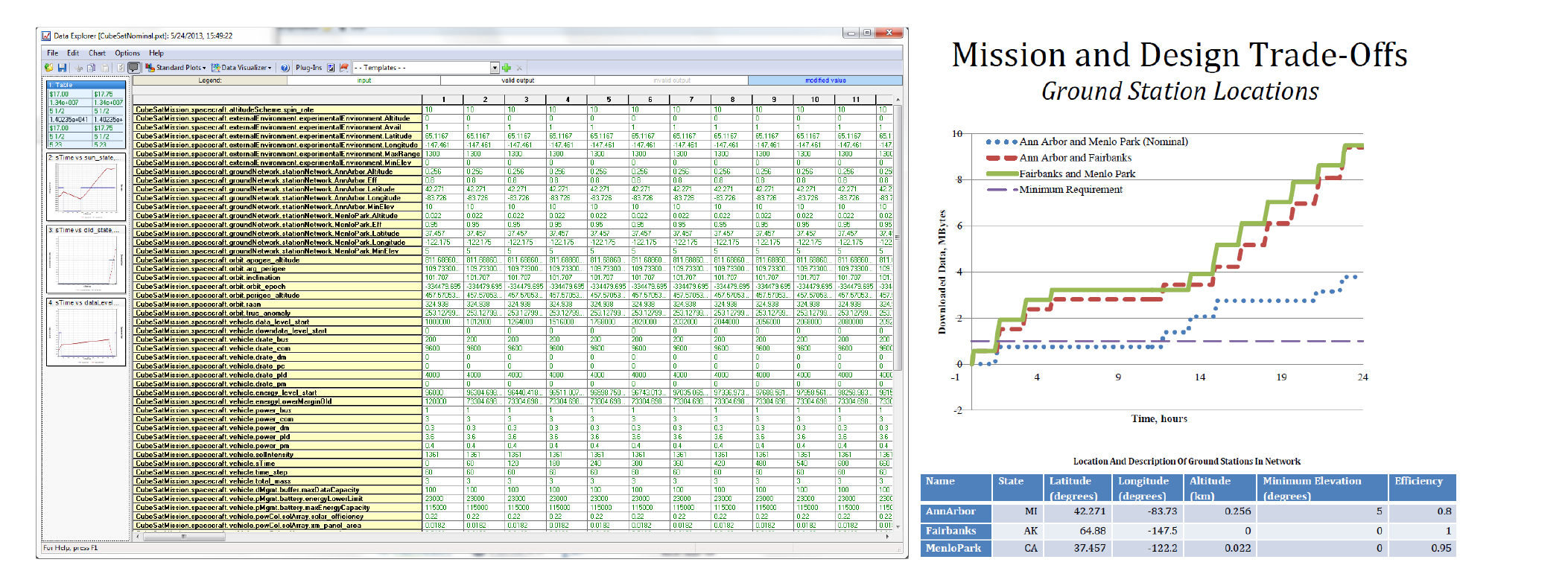
The first of such activities is requirements derivation. Following the concept stage, the initial CubeSat project goals are to be refined into specific requirements. This is an iterative process to explore the trade space of system designs. With the model fully connected, we can orchestrate large-scale trade studies on all spacecraft subsystems (Figure 5.6): vehicle sizing, power requirements, payload selection, data management, command and control options, etc. More importantly, through the connected model, the impact of any design change on the adjacent systems is immediately traceable. The results of those trades and optimization studies feed directly back to validating and/or updating the requirements, enhancing system design strength.
Advancing in the engineering lifecycle, the system model gains complexity and the system software elements grow accordingly. In the CubeSat project, communication models are improved from a basic line of sight link model (at the start of the project) to a complex communications link budget analysis (as the project matures) that employs custom antenna models, with transmitter power, frequency and filter modeling and propagation loss models. Power budgets are improved from initial estimates to detailed solar panel studies and sensor/payload/communications power load analysis. Eventually, that detail grows to include DevSecOps software to drive the logic of individual systems – for example, the CubeSat onboard systems will have to make decisions when to collect data versus when to downlink, based on available power and storage. The software is developed as an integrated component in the model, immediately testable in the mission environment. The ModelCenter MBSE link enforces consistency between the model and software – as either the descriptive model or the software matures, it forces that update to be reflected in the other in order to remain connected and executable.
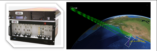
Eventually, the engineering phase transitions to development and deployment of physical systems. As individual hardware or software components are constructed, their software is extracted from the latest model. In this way, we have now extended the traceability even further, beyond just simulated performance and now into functional systems. As hardware or software components are developed, their functionality and performance can be tested “in-the-loop” using the embedded simulators that are part of the Digital Thread (Figure 5.7). Our SysML-based Digital Thread has effectively been translated into deployed systems hardware and software.
An added benefit of the fully connected Digital Thread is that it effectively becomes its own virtual test harness. As the earlier stages of development were connected to the authoritative model, the hardware will necessarily support the same software interfaces. This enables a connection from the hardware back to the virtual test scenarios employed in the software development phases. Similarly, user interfaces and physical controls can be tested in full mission simulations.
Finally, the system is fielded and enters the sustainment phase. Operators frequently overlook the value of the engineering models or are not provided access to them. In cases where anomalies are experienced, there is infinite value in having a true digital twin available for the fully deployed system. This model makes possible the forensic analysis of observed behavior or troubleshooting and discovery of potential solutions. Also, mission parameters tend to change more rapidly than new systems are deployed; operators are consistently challenged with using existing resources in new and innovative ways. The executable system model framework lets operators experiment with systems down to the lowest hardware and software level and assess the potential mission impact.
Providing operators access to this model formally includes them in the engineering process and completes the feedback loop. The follow-on development requirements will have direct input from the end users who may often contribute to the solution as well.
It is well understood that the lifecycle management of hardware and software systems is a complex problem but there are steps that can be taken now with available tools and processes to bridge the gaps and connect the entire digital engineering enterprise. Those steps are: Couple formal descriptive models with mission simulations; use the output of the simulations to inform/update the models; and use them both to drive functional and performance requirements. The development team builds software integrated into the modeling environment, directly linked to those requirements. The formal model is continually executed, calling the development software and models, testing components and verifying requirements. The code is assembled for delivery from the model. The system delivered is guaranteed to match the system described in the model.